


7′ x 20′ Outside Frame Box/Fruit Car Progress
Since the 7′ x 20′, outside framed, box and fruit/stock car kit projects are long term projects and since we can’t make every convention to show off progress on these project; we decided to put up this page as a kind of progress report. (A two man company has to spend a lot of time doing everything from book-keeping to research & development to production work to being the janitor, so projects with lots of molds take a lot of time.) We’ll keep adding to it as more parts are finished. And we think we’ve learned what we needed to learn to reliably fill the parts and get them out of the molds. So, the pace should pick up a bit. Stay tuned!
Inspiration (2011, 2014):
The inspiration for this car came many years ago after encountering the Virginia & Truckee’s outside braced combination box car number 1005, fully restored at the Nevada State Railroad Museum in the early 1980’s. We’ve been unable to find our own photos of the car, but photos and histories of the car can be found at the following links: V&T Box Car No. 1005 and Virginia & Truckee - Box Cars. Being 29′ long, it has space for both regular and ventilated doors as well as room for sliding vertical doors for loads like grain, that our 20′ car doesn’t. But, there’s a lot to like, including the yellow ochre paint!
Jerry Kitts built his pilot model in the fall of 2011. Starting off with a 20′ Flat Car kit FMW-2214, he used MacLeod Western T-18-1 trucks (for a fun change of pace), parts from a MacLeod Western D-3006 SPC 24′ and 28′ Box Car Hardware Detail Set, Grandtline Products #95 Narrow Gauge Stock Car Post and Brace Feet, and various Evergreen Styrene sheets and strips to build his outside framed box car shown here. A fun, but prototypical, little car!
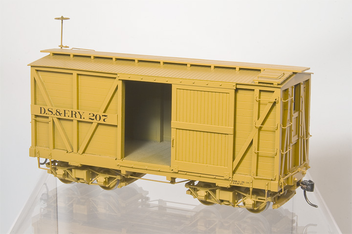
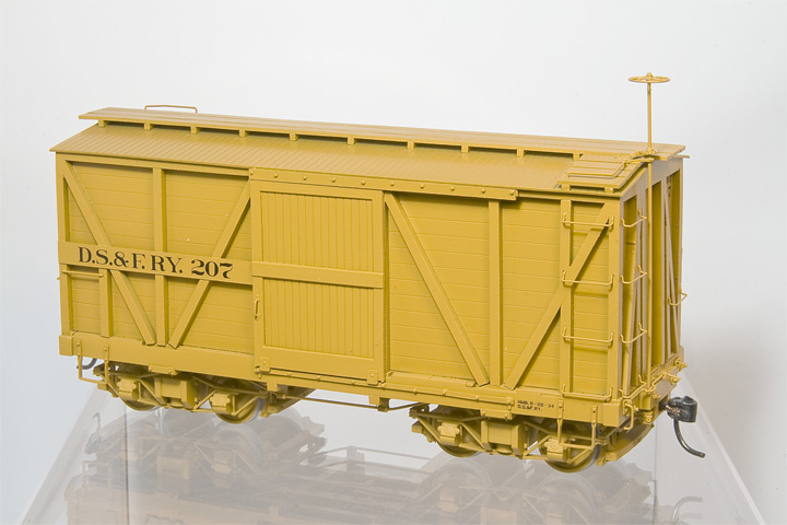
Pilot model built by Jerry Kitts, fall of 2011.
Following up, Jerry Kitts built this pilot model of the fruit car in the summer of 2014. Starting off with a 20′ Flat Car kit FMW-2214, he used MacLeod Western T-18-1 trucks (for a fun change of pace), a MacLeod Western D-3004 SPC Ventilated Box Car Detail Set, using our new side and end framing parts in stead of Grandtline Products #95 Narrow Gauge Stock Car Post and Brace Feet, and various Evergreen Styrene sheets and strips to build his fruit car shown here. Now all it needs is hundreds fruit crates!
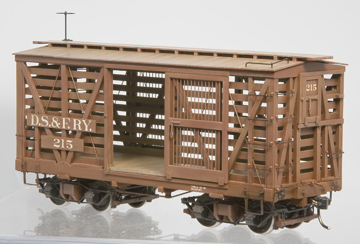
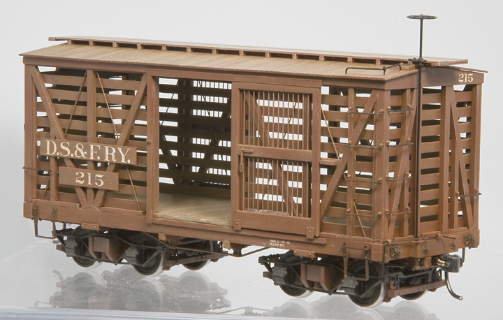
Pilot model built by Jerry Kitts using side and end framing parts, summer of 2014. Roof not attached as weathering isn’t finished yet.
Research & Development (Winter 2012–2013):
Now that we had an idea of what we wanted to make, it was time to hit the books. It’s “easy enough” to cut a die for any fantasy you can dream up; but that’s not what we do here at Foothill Model Works. While there is no specific prototype for these cars, our car kits do follow all the correct building practices of the day. So they “could have been.” This is especially important for an outside framed car, where all the details of the framing are out in the open!
Luckily, there are several great references that are still available, that go into great detail on 19
|
|
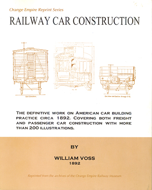 Voss, William, The Orange Empire Reprint Series: Railway Car Construction, by William Voss 1892. (Perris, California: Orange Empire Railway Museum, 1999). The blurb on the cover says it all: “The Definitive work on American car building practice circa 1892. Covering both freight and passenger car construcion with more than 200 illustrations.” If you have any of the Trainshed Cylcopedias on 19
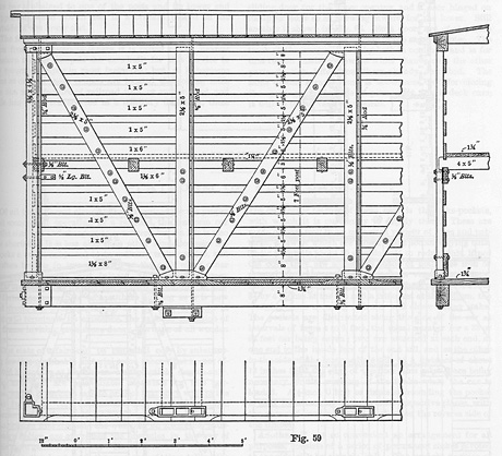
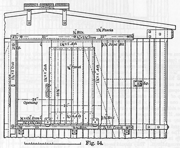
Figures 59 and 54 from pages 45 and 40 of Railway Car Construction, by William Voss 1892.
|
|
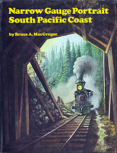 MacGregor, Bruce A., Narrow Gauge Portrait South Pacific Coast. (Felton, California: Glenwood Publishers, 1975). Generally, a history of the South Pacific Coast Railway, but it includes some history of Carter Brothers, makers a lot of original west coast narrow gauge equipment and a series of drawings showing Carter Brothers construction techniques. The best part about this book is that it came with two 16 1/2″ × 22″, folded, reprints of Carter Brothers construction notes for the SPC’s 28′ Box and Combination Box cars, as well as the WSF&LCo.’s 24′ flats. Complete with sketches of parts with dimensions! (Out of print, but can be found for $42.)
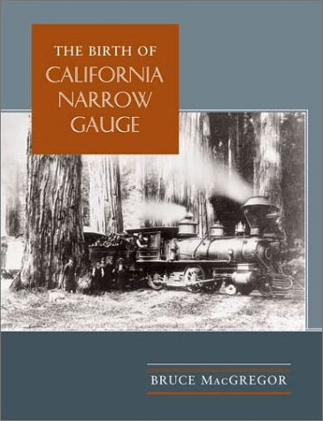 MacGregor, Bruce A., The Birth of California Narrow Gauge: A Regional Study of the Technology of Thomas and Martin Carter. (Stanford, California: Stanford University Press, 2003). A history of Carter Brothers, builders of musch of the West Coasts’ early passenger cars, flat cars, and box cars. Includes many photos and drawings. I’ll make it easy for you; if you model west coast narrow gauge or early standard gauge (SPC, NPC, NCNGRR, SPng, PC, SC&F, M&SV, WSLCo., etc.), you need this book. (The hardcover edition can still be found new for $54.)
And since the fruit car was inspired by early D&RG stock cars (as well as the NCNGRR’s fruit cars):
|
|
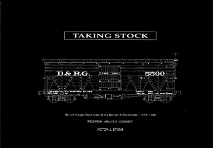 Stone, Victor J., Taking Stock; Narrow Gauge Stock Cars of the Denver & Rio Grande: 1873–1968; RESEARCH:ANALSYS:COMMENT. (Hampshire, England: Creedstone Publications, 1992) 10-33. History, D&RG drawings, photographs, diagrams, stock movements. Complete information on every single one of the D&RGW’s 902 narrow gauge stock cars. A great book to own, even if you don’t model the Rio Grande. The chapter on 19
We also used the AAR’s (the Association of American Railroads, formerly the Master Car Builders’ Association or MCB) published safety appliance standard from around the turn of the (20
So, you combine all this stuff together: Carter Brothers parts, Voss’ construction techniques, AAR safety requirements, and the real world examples of NCNG, SPC, D&RG equipment; and you come up with the following set of drawings for the two cars. (It’s a layered drawing that includes cross sections and roof framing that isn’t shown here for clarity’s sake.)
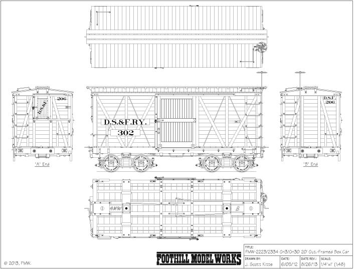
Working Drawing of Final, Outside Framed Box Car.

Working Drawing of Final, Outside Framed Fruit/Stock Car.
But, we’re not done yet. Now we have to separate out like parts into logical groups, make adjustments for things like plastic shrink, and make additional CAD drawings for the tool paths to be used in our CAM software. The CAM software is then used to generate the G-Code used to drive the CNC mill. We can then, finally, start making metal chips!
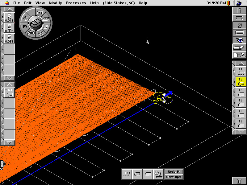
Generating the tool paths in Virtual Gibbs, our CAM software. (In this case, the Plexiglas patterns for the Polyurethane version of the side stakes for the 20′ Ore Car kit. Yes, these screen shots go back a bit, but the concept is the same.)
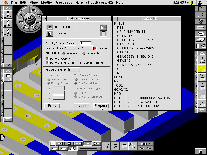
Generating the G-Code from finished tool paths.
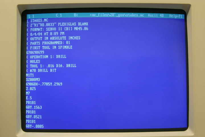
Finished G-Code awaiting machining.
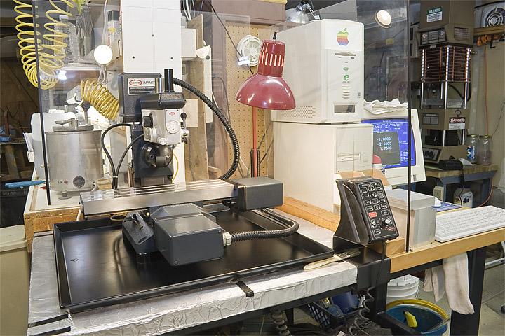
Our Servo Impact System II CNC Mini-Mill in a most unnatural state – clean.
Some Injection Molding Terms:

Our Morgan Press injection molding machine back when it was new, clean, and pretty.
As long as we’re talking about injection molding parts, we might as well define some terms you may, or may not, already be familiar with (nor able to find correctly defined, if at all, in most dictionaries).
| sprue |
a channel through which metal is poured or plastic is injected into a mold. This can refer to the entire system of channels leading through the die block or (more commonly) just the first section of channel leading from the injection nozzle, through the die block, to the parting line of the die block and the beginning of the system of runners, on the inside of the mold. (Not the disease.) • a piece of metal or plastic that has solidified in a sprue, esp. one joining a number of small molded plastic items. |
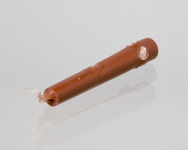
Examples of sprues.
Modelers never see the type of “sprue” shown above. They’re always cut off before the parts are sent to customers. In fact, these were the only examples I could find in the entire shop when I shot these pictures. They make the parts hard to stack together and they usually have a long, annoying, stringy hair of plastic trailing off of the tip too.
We’ll use the second definition of a whole set of parts connected by runners.
| run • ner |ˈrənər| noun — | a smaller channel that diverts molten plastic from the sprue to the individual part. This can refer to the last section of channel leading to the gate or (more commonly) to the entire system of channels leading from the main sprue. |
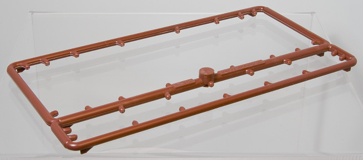
Example of the system of runners from the side framing mold.
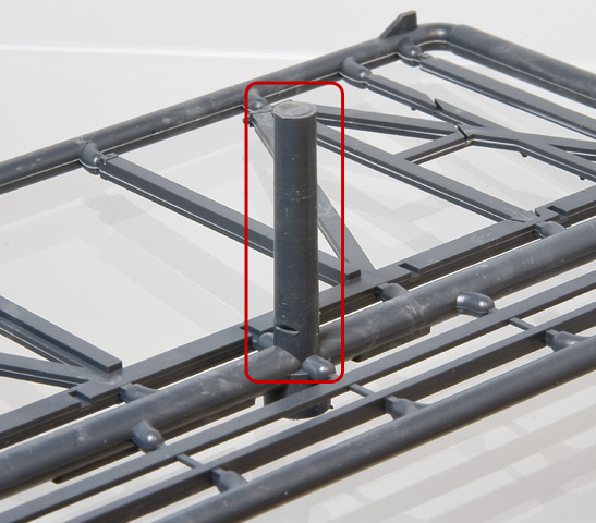
| gate |gāt| noun — | the location at which the molten plastic flow is restricted as it enters the mold cavity of the part and is often seen as a small blemish or nub or projection (the “gate mark”) on the molded piece. |
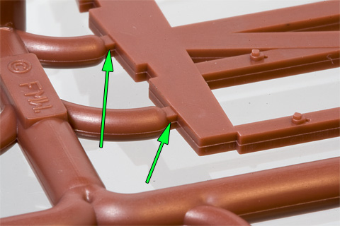
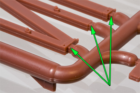
Examples of gates.
Side Framing Mold (September–August 2013):
Side frame sprue consists of the purlins, and the side frames (from the side plates, down through the posts and braces, to the post brackets). Slots to position the tie rods are cast in place as well as detents that serve to locate the holes for the grab iron ends. All of the gates are positioned so that they will be hidden on the finish model.
| pur • lin |ˈpərlən| noun — | a horizontal board along the length of a roof, resting on the carlins, that serves as a nailer for the roof boards. |
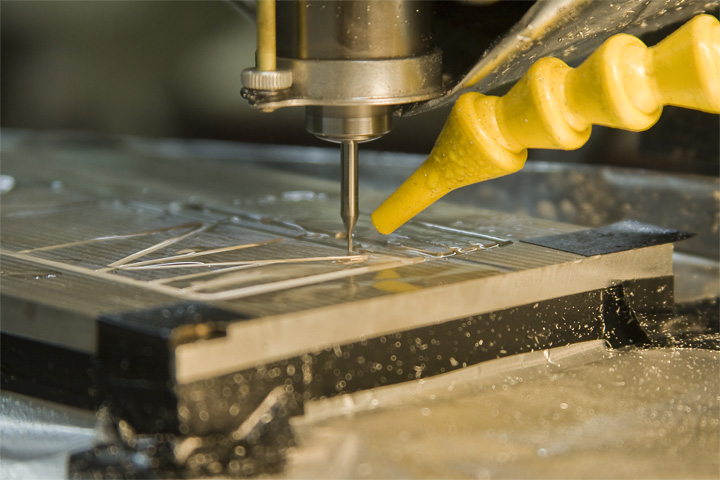
Action Shot! Side Framing Mold being machined. The yellow LOC-LINE is spraying air and a water-based “coolant.” Which gets everywhere, hence the aluminum foil taped around the block - to collect the coolant for reuse and to keep it out of the ways of the mill, as our bench-top CNC mill lacks the wet cabinet used to contain the coolant used on most larder mills. (Special treat: the “bio-degradable” rust inhibitor, bio-degrades in the heat of the summer; just like apple juice.) By the way, that’s a 1/32″ (0.03125″) diameter end mill “rough-cutting” out the fascia board. The finish cut will be done with a 0.010″ diameter end mill.
I made some mock-ups of the two different car’s sides to give a general idea as to how the finished cars should look. I used Evergreen styrene strips and MacLeod Western SPC ventilated box car doors as stand-ins for our future parts. SPC ventilated box car doors were used because they are standard, Carter Brothers doors, which our kits will also use.
Mock-up of Outside Framed Box Car side, using Evergreen Styrene and MacLeod Western SPC Box Car Door built on side frame sprue.

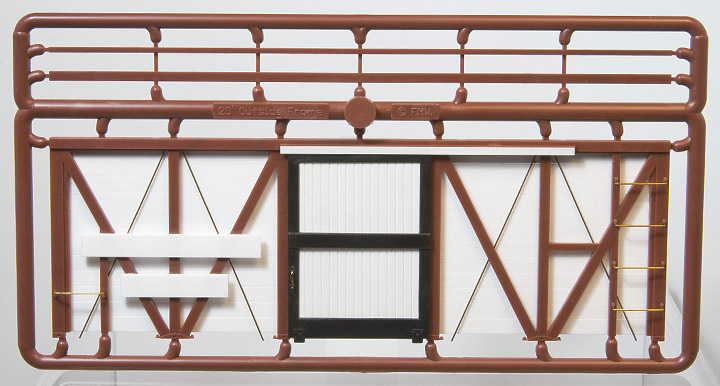
Mock-up of Fruit/Stock Car side, using Evergreen Styrene and MacLeod Western SPC Ventilated Door built on side frame sprue.
End Framing Mold (May–June 2014):
End frame sprue consists of the carlins, and the end frames (from the end plates, down through the posts and braces, to the post brackets). Detents that serve to locate the holes for the grab iron ends. All of the gates are positioned so that they will be hidden on the finish model. The slots in one of the carlins and in the end plates are designed to allow the roof, assembled with the purlins and remaining carlins, to be removed from the completed model, to allow for painting the interior.
| car • lin |ˈkärˌlən| noun — | a board that extends from one side plate to the other, placed at proper intervals, that serves as a support for the purlins; a roof rafter (not the old hag, witch, or thistle). |
We use a small, high precision, CNC bench-top milling machine with a spindle run-out of 0.0002″ TIR and a linear positioning repeatability of ±0.0002″. (Typical CNC machining centers run at least ten times that amount.) On the plus side, that means that we can machine some very intricate details into our molds; on the down side, we can’t put a lot of horse-power into a cut and we typically use VERY small end mills to cut the features (0.010″ in diameter on this one, though we have used clear down to 0.003″ – which is the thickness of a typical piece of paper, or an 1/8″ in O scale). This results in some fairly long machining times. This mold took about 116 hours to machine. In case you’re curious, we hand strip the parts from the mold. We don’t use a screw press with ejector pins. We use a manual, vertical, pneumatic plastic press.
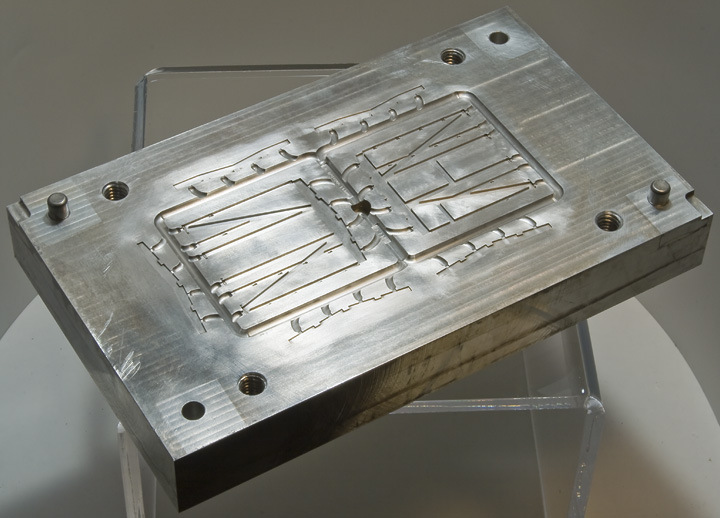
Half of completed ends framing and carlin mold.
You gotta love it when everything goes right! We get a perfect part every time at a low temperature and injection pressure. (Good quality plastic always helps too.)
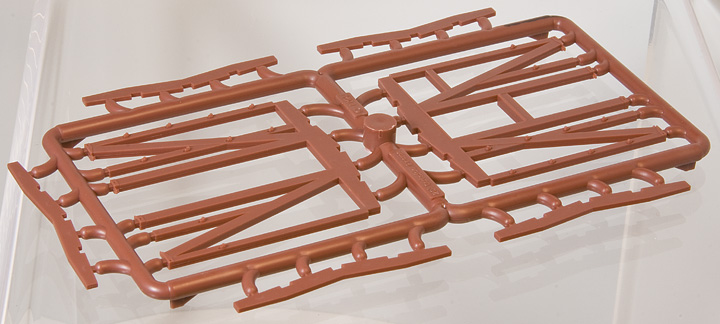
Ends framing and carlins sprue fresh out of the mold.
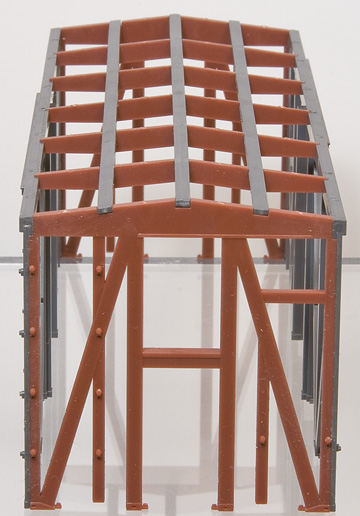
The first set of test shots assembled are shown below. No attempt to remove parting lines or gate marks has been made. Though the parts appear to be fiddly and fragile, the assembly is surprisingly sturdy. The tightly controlled casting of the parts also made assembly easy.
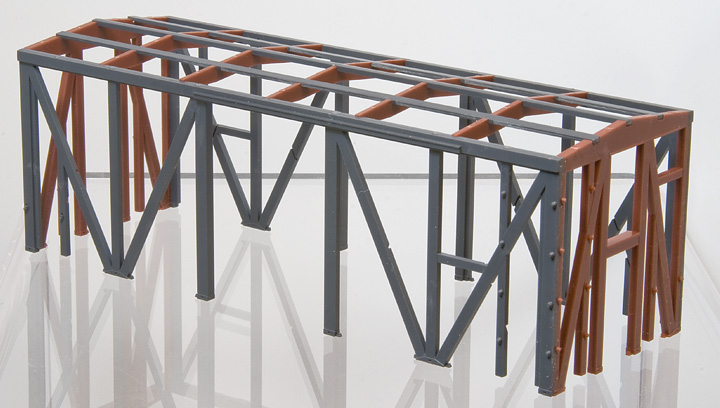
Test shots assembled.
The parts are designed so that the finished car will have a finished, scale, prototypical interior.
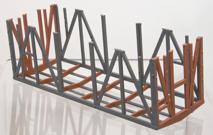
Test shots assembled, up-side-down.
As you can see, the parts were developed so that the roof could be removable for painting. The removable roof framing parts will eventually be glued to the roof and roof walk parts. The idea being that these roof parts will be glued in place after painting.
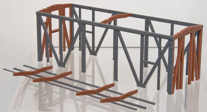
Assembled test shots with removable roof framing parts removed.
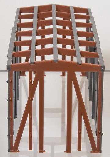
Assembled test shots end views. The end facias will be a separate part and will cover the ends of purlins and the notches in the end plates, and the gate marks in the end of the side plates.
On to the deck! Stay Tuned for More!
All text, images, and drawings ©2014, Foothill Model Works.
Rev. 8/05/2014.